
Tec-Alert Newsletter
Cable Termination, Part 1
Key Steps and Proper Tools for Copper IDC, Coax and Fiber Termination: Part 1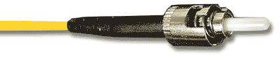
Cable Termination is the connection of the wire or fiber to a device, such as equipment, panels or a wall outlet, which allows for connecting the cable to other cables or devices. The three main areas we will discuss are termination used in Telecom, Datacom and Fiber Optic industries. This involves the organizing of cables by destination, forming and dressing cables, and proper labeling as well as creating a connection with a copper or fiber conductor.
In order to begin, there is planning that must take place. Prepare for the termination by developing a strategy for the cable beginning and end, making sure you have the proper tools to complete the job. Remember the cable connection is not complete until all terminations are properly identified and labeled!
Preparation:
Making careful preparations before cable termination takes place will ensure that the job is done properly, and will save you time and money from the onset.
Begin by determining where the termination point is located. If unknown, make sure each cable will reach the farthest point in the wiring closet or equipment room. Next, route the cables to this area making sure the cable length is correct as well as labeling each cable as you go so you can identify it later. Then form and dress the cable by ensuring that all cables are parallel to each other, shaping them into neat bundles using hand tightened cable ties or hook & loop wraps. If a cable is too long, make sure to remark the newly created end the same as before. Once the termination area is set up, use the proper cable management hardware to act as the support and relief. This is important since some cables have specific minimum bend radius requirements. Knowing this will protect the integrity of the cable being installed.
Now you are ready to start!
PART 1: Copper IDC and Coaxial Cable Termination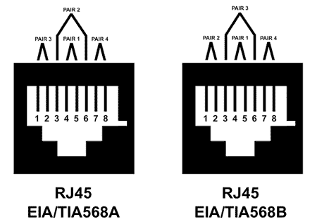 Copper IDC Termination:
Insulation Displacement Connection (IDC) termination is the recommended method for copper termination recognized by ANSI/TIA/EIA- 568-A for UTP cable termination.
Key Steps:
Step 1: Determine method and length of sheath removal. There are several types of tools to choose from when performing sheath removal. The tool you use will depend on your personal preference, your budget, the types of cabling you are using, etc. We will highlight some options in the tool section. Step 2: Remove only as much of the sheath as necessary to terminate the cable pairs and ensure that the twist of the pairs is maintained. Depending on the block, type, size of the copper cable and type of IDC termination hardware manufacturer, the requirements will differ for the correct length to be removed.
Step 3: Separate, identify, and tie off binder groups. This refers to 50 pair and larger pair-count cables. By keeping each binder group separated and tied off, it will assist in the termination and allow for easier housekeeping. Step 4: Fan out and form cable pairs from each binder group. Pairs should not cross or interfere with any other pairs. Also, wire pairs should be parallel with no tension at the point of connection, and equal tension on all connections.
Step 5: Now you are ready to fix to a termination block (a) or crimp to a modular plug (b).
Step 5a: Termination blocks are hardware designed to house the cable mainly for Telecom and Datacom applications. Although there are many types of termination blocks, the most common termination blocks are 66- or 110-style. The 66-Block mainly is used for voice applications in PBX, Key Telephone Systems and some LANs. The 110-block is used in both voice and data cabling applications. Using a 66-block the twisted pairs are fanned through one by one and punched down onto the block for termination. Using a 110-block, the wires come through the center and fan out being punched down into each slot in the block for termination.
Step 5b: When termination onto modular plugs, such as your RJ11, RJ45 and Cat5, you simply feed the twisted pair wires into the connector while keeping each wire parallel to the next avoiding overlap. Using a ratcheting crimp tool with the proper crimp die, you simply squeeze the handle until you have made a secure crimp.
NOTE: Tecra Tools strongly recommends the use of a RATCHETING crimper for all connector terminations! This will help ensure consistency, eliminate over- or under-crimping and reduce hand stress.
Tools for Use with Twisted-Pair Cables: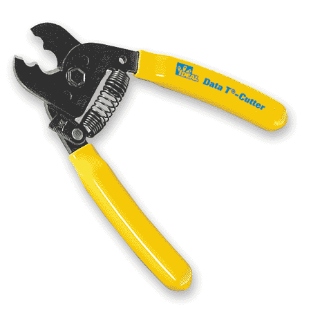
Cable Cutting Tools
You will need a variety of cable cutting tools depending on the size of cable you are working with. For small cables a diagonal flush cutter or round cable cutter works best. Larger cables require a high leverage cutting tool or even a ratcheting cable cutter.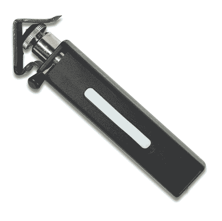
Sheath Removal Tools
Ringing Tool, electrician snips, and slitter tool all provide a way to remove the sheath on a UTP cable but each in different ways. The ringing tool is the most reliable as it is preset to only cut the thin outer sheath without damaging the wires underneath. While electrician's snips are a required trimming tool for any termination job.
Punchdown Tools
Select high quality punchdown tools with the proper blade for the type of termination block being used (66, 110, Krone, Bix, etc.). Don't skimp on this tool! You will find yourself using it constantly.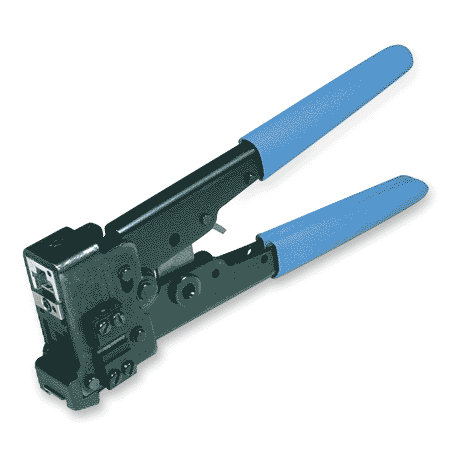
Crimping Tools
Use only a ratcheting crimp frame with the proper crimp dies for the plugs you are using, RJ-11, RJ-45, Cat 5, etc.
NOTE: Cat 5 plugs often differ from typical RJ-45 plugs in that the Cat 5 plugs have no secondary strain relief indention in the plug body. This is done to help maintain the twist in the wire pairs as they move through the plug body. If you are using Cat 5 plugs like this, you will need to use our Cat 5 crimping dies when crimping these plugs. Failure to use the proper Cat 5 die will crush the plug body and ruin the connector.
Coaxial Cable Termination: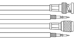 Coaxial cables consist of an inner conductor (solid or stranded wire), separated by a dielectric (core) from its outer conductor (single or double-braided shield) and covered with PVC or plenum rated outer sheath. This type of cable is basically used for audio/ visual but can support data. The predominant coaxial cables are RG-6, RG-11, RG-58, RG-59, and RG-62.
Key Steps:
Step 1: Determine the proper method and length of sheath, braid, dielectric and center conductor removal. Start by making a straight cut in the termination end of the cable. Next, place connector ferrule over the end of the cable. Adjust the two- or three-step coax stripping tool to meet the desired cable diameter and stripping requirements. Insert cable into the striper, rotating the stripper 3 to 5 full turns. Remove the severed sheathing, shielding and dielectric material while inspecting the strip quality, making sure there are no stray strands of braided shield, nicked center conductor or damaged insulation.
Step 2: Terminate the cable by seating the connector system pin on the center conductor. Crimp the pin onto the center conductor using a dedicated center pin crimping tool or the, less desirable, small diameter die nest of the crimping tool.
Step 3: Insert sleeve and connector onto cable. First place the connector body onto the cable by aligning it so that its shaft fits over the center conductor pin and between the dielectric and the braid shield. Slide the connector ferrule up to cover the exposed braid shield. Place the crimp tool over the connector ferrule and squeeze the tool until the die is completely closed. The connector must be tight so inspect the connection for its neatness and snugness.
NOTE: Using the correct crimping die size is critical to proper coax termination! This size is only determined by the type of connector used NOT the size of the cable! When specifying the proper crimping die, refer to the connector manufacturer's specification for the recommended crimp sleeve diameter.
NOTE: Tecra Tools strongly recommends the use of a RATCHETING crimper for all connector terminations! This will help ensure consistency, eliminate over- or under-crimping and reduce hand stress.
Tools Used for Coaxial Cable Termination: Cutting Tools
A good set of coax cable cutters and flush cutters is required when termination coax cabling. Be careful not to try cutting steel center conductors with a tool designed only for cutting copper. We recommend the use of a center conductor cutter specifically designed for this purpose.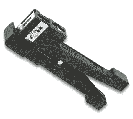 Coaxial Stripping Tools
There is a large variety of coax stripping tools available; preset, adjustable, two-step, three-step, etc. For most purposes an adjustable three-step stripper will work best for the widest range of cable and connector types.
Coaxial Crimping Tools
Rule 1: Always buy ratcheting!
Rule 2: Get a crimper with interchangeable dies. Don't buy an entirely new tool everytime you need to crimp a new type of connector!
Rule 3: Crimp the center pin on with a dedicated center pin crimper. Don't use the small crimp nest of your crimp sleeve crimper! It simply won't deliver the reliability of an 8-point or 12-point indent crimper.
Rule 4: Know the proper crimp sleeve diameter for your connector and use the matching die. Over- or under-crimped connectors are failures waiting to happen!
Click here to see Part 2 of our Cable Termination Series: Fiber Optic Termination.
Go to back to Tec AlertReturn to Top of Page
BUILD YOUR OWN TOOL KIT
Subscribe to our Tec-Alert Email Newsletter
Get tips & information for field service and MRO professionals.