
Tec-Alert Newsletter
Cable Termination, Part 2
Cable Termination Basics: Key Steps and Proper Tools for Copper IDC, Coax and Fiber Terminations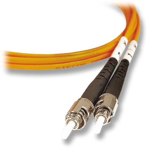 Cable Termination is the connection of the wire or fiber to a device, such as equipment, panels or a wall outlet, which allows for connecting the cable to other cables or devices. The three main areas we will discuss are terminations used in Telecom, Datacom and Fiber Optic industries. This involves the organizing of cables by destination, forming and dressing cables, and proper labeling as well as creating a connection with a copper or fiber conductor. In order to begin, there is planning that must take place. Prepare for the termination by developing a strategy for the cable beginning and end, making sure you have the proper tools to complete the job. Remember the cable connection is not complete until all terminations are properly identified and labeled!
Preparation:
Making careful preparations before cable termination takes place will ensure that the job is done properly, and will save you time and money from the onset.
Begin by determining where the termination point is located. If unknown, make sure each cable will reach the farthest point in the wiring closet or equipment room. Next, route the cables to this area making sure the cable length is correct as well as labeling each cable as you go so you can identify it later. Then form and dress the cable by ensuring that all cables are parallel to each other, shaping them into neat bundles using hand-tightened cable ties or hook & loop wraps. If a cable is too long, make sure to remark the newly created end the same as before. Once the termination area is set up, use the proper cable management hardware to act as the support and relief. This is important since some cables have specific minimum bend radius requirements. Knowing this will protect the integrity of the cable being installed.
Now you are ready to start!
PART 2: Fiber Optic Cable Termination
Optical fiber cable has become the new standard in the telecommunications world as it delivers a much lower signal loss than copper cabling. By the use of light generated by a laser or a light-emitting diode (LED), a signal is carried through the cable. An optical fiber is made up of two distinct elements known as the core and the cladding. Both are made of glass, the difference is in the amount of additional padding or dopants added to the glass during the manufacturing process to alter the index of refraction. The changes in refraction between the core and cladding enables the optical signal (light waves) to remain within the fiber core. This enables the light to travel vast distances with very little signal loss.
There are two main types of fiber optic cable: Multimode and Singlemode. Each type has it's own characteristics. See our fiber optic technology section for further explanation-
Before we begin with the fiber optic termination steps, we must first note that there are at least four methods used for fiber termination: Heat-cured, UV light –cured, crimp and anaerobic termination. In this article, we will only cover anaerobic termination using SC or ST connectors onto 3mm jacketed fiber.
Key Steps for Anaerobic-Style Termination of Optical Fiber Cable:
Step 1: Slide the 3 mm boot followed by the crimp collar down the fiber until out of the way. Remember that each manufacturer of fiber optic connectors has different instructions for use, so make sure to read the instruction manual prior to terminating any fiber. Step 2: Using the proper tool, sever the jacket or sheath and remove it from the cable.
Step 3: Measure and mark the aramid yarn the specified distance from the end of the fiber. Step 4: Carefully mark the correct length of buffer to be removed following manufacturer's specs. Strip the buffer to the mark to obtain a specified amount of bare fiber. Clean the bare fiber using two passes with a lint-free alcohol wipe (99 percent pure). Do not touch the bare fiber after this point.
Step 5: Insert the syringe tip into the rear of the connector assembly until it bottoms on the ferrule. Slowly squeeze the adhesive into the connector until the adhesive appears on the tip of the ferrule. Withdraw the syringe slowly while continuing to lightly squeeze adhesive into the barrel of the connector. Step 6: Set aside the connector and paint the bare fiber with the primer (catalyst). Ensure that the bare fiber, as well as the exposed buffer coating is primed for insertion. It is very important to paint on the primer and not dip the bare fiber into it as pieces of the bare fiber could fall into the primer creating a safety hazard.
Step 7: Carefully and steadily, insert the fiber into the connector until the connector reaches the buffer tube. Using Tecra Tools' anaerobic adhesive kit, the curing time is only 30 seconds for the catalyst to take affect and the adhesive to harden. Step 8: Slide the crimp ring up the buffer tube and then fan out the aramid yarn around the connector base being extremely careful. Crimp the ring onto the body of the connector in one or sometimes two crimps (check connector specifications to determine the proper crimp diameter).
Step 9: Slide the boot up the jacket to the back of the connector and over the crimp ring. Step 10: Using a fiber scribe, score the excess fiber where it emerges from the adhesive bead on the ferrule tip. Gently and carefully pull the fiber straight up to remove excess fiber. Safely dispose of the excess fibers in a fiber scraps trash can.
Step 11: Clean the surface of a rubber or plastic polishing pad with alcohol followed by a lint-free tissue. Blow surface dry with canned air. Check connector to see which pad you should use. Step 12: Place polishing film over polishing pad. Insert connector end into a universal polishing puck. Lay puck over film, making figure 8s on the rose color 3-micron film then repeat the process on the white 0.3-micron fine film. When complete, the surface should have a mirror finish with the edge of the fiber face
perfectly circular.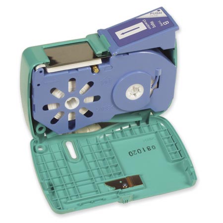 Step 13: Clean the end face of the ferrule with alcohol or solvent-free CLETOP reel cleaner and check for visual imperfections or scratches with a fiber optic inspection scope. After passing visual inspection, place a dust cover over the end of the connector ferrule.
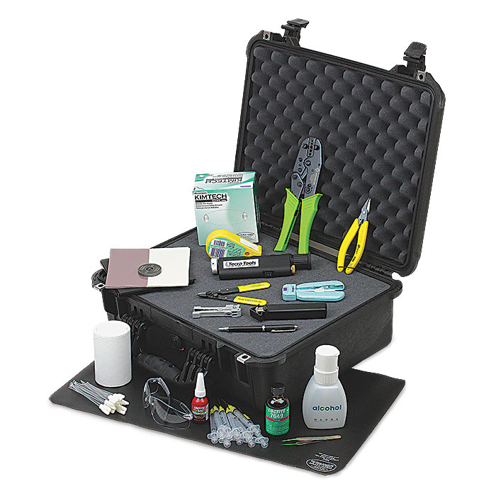
Tools to use for Optical Fiber Termination:
This how-to article was designed to be used with Tecra Tools Fiber Optic Termination Kit #84855.
Click here to see the details of this Fiber optic Termination Kit.
If you need individual tools for fiber optic termination, click here.
Go to back to Tec Alert
BUILD YOUR OWN TOOL KIT
Subscribe to our Tec-Alert Email Newsletter
Get tips & information for field service and MRO professionals.