
Tec-Alert Newsletter
Digital Multimeter Basics
 There are hundreds of styles and models of Digital Multimeters on the market today. Technology is constantly changing, these days it seems everything is controlled by electronics. Servicing, repairing and installing this complex equipment requires diagnostic tools that will give you accurate information.
It is hard to know which one will best fit your needs until you really know the basics of DMM functions. In this article we will break down and define the typical Core Functions found on a DMM and explain their importance. In addition, we have created a quick Reference Comparison Chart to compare the various DMM models we keep in stock to assist you in finding the best match for your needs. We wrap it up with important DMM Safety Tips to keep you and your meter safe and in good working order.
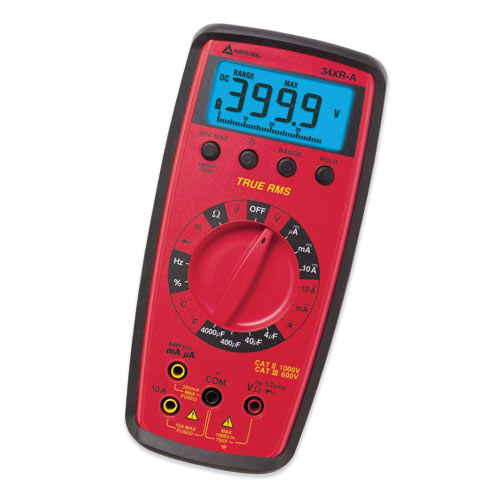
What is a Digital Multimeter (DMM)? A DMM is simply an electronic ruler for making electrical measurements. The multimeter combines the functions of a voltmeter, ammeter and ohmmeter. It may have any numbers of special features but mainly a DMM measures volts, ohms and amperes.
Important Features to Consider
Resolution
By knowing the resolution of a DMM you can determine whether the meter could measure down to only 1 volt or down to 1 millivolt (1/1000th of a volt). The resolution refers to how small or fine a measurement the meter can make. You wouldn’t buy a ruler marked in one-inch segments if you needed to measure down to 1/4 inch mark. A 3200-count meter will display a tenth of a volt resolution up to 320 volts. This is the same resolution as a more expensive 20,000-count meter until you exceed 320 volts.
Accuracy
Accuracy is the largest allowable error that will occur under specific operating conditions. This shows how close the DMM’s displayed measurement is to the actual value of the signal being measured. An accuracy reading of ± 1% of reading means that for a displayed reading of 100.0V, the actual value of the voltage could be anywhere between 99.0V to 101.0V.
Analog Bar Graph
A bar graph image on the meter that shows the changes and trends in a signal just like an analog needle. The analog needle display that is less accurate than a digital display and has lower effective resolution since you have to estimate values between the lines. Typical analog accuracy is 2-3% of full scale whereas a digital meters accuracy is typically 0.7-0.1% of the reading or better!
Voltage
The most basic function of a DMM is measuring voltage. A generator creates AC voltage while the source of DC voltage is a battery. Voltage measurements determine source voltage, voltage drop and voltage imbalance. Using the test probes with your meter, you can determine the amount of voltage present. Make sure you are in the right mode and that the black lead is plugged into the common (COM) input jack and the red lead is plugged into the V Input jack. DANGER: If you are still plugged into the current jack, serious damage to the meter will occur. The red lead touches the positive side of the circuit and the black lead touches the negative. If you mix up the red and black on the circuit, the DMM shows a negative reading. REMEMBER: If you are testing high voltage, you will need high voltage probes.
Current
Current measurements determine circuit overloads, control circuit current (4-20 mA current loop), circuit operating current, and current in different branches of a circuit. Voltage and resistance measurements are made in parallel whereas current measurements are made in series. The entire current being measured flows through the meter! IMPORTANT: the test leads must be plugged into the proper jack based on the expected value of the reading, black lead (COM) and red lead (10 AMP or 300mA). Also, turn off power to circuit before testing. Once the tips are making contact, switch the power back on to view the reading.
Resistance
Resistance measurements determine resistance of a load, resistance of a conductor, value of a resistor, and operation of a variable resister. This is measured in Ohms and must be made with the circuit power off. The resistance values can vary greatly, from a few milliohms for contact resistance to billions of ohms for insulators. Select resistance, plug black lead into COM input jack and red into the Ohm jack. Place tips across the component or portion of the circuit for which you want to determine resistance.
Capacitance
In a capacitor or system of conductors and dielectrics, the property that permits the storage of electrically separated charges when potential differences exist between the conductors. Capacitance is related to voltage as follows: C = Q/V where C is the capacitance in farads, Q is the charge in coulombs, and V is voltage in volts.
Frequency
For an oscillating or varying current, frequency is the number of complete cycles per second in alternating current direction. The standard unit of frequency is the hertz, abbreviated Hz. If a current completes one cycle per second, then the frequency is 1 Hz; 60 cycles per second equals 60 Hz (the standard alternating-current utility frequency in some countries).
True-RMS
The RMS value is the Root-Mean-Square of AC waveforms, sinusoidal (sine waves) or non-sinusoidal (sawtooth, square, ripple, etc.). The RMS value is the effective or equivalent DC value of the AC voltage. Average meters only give an accurate RMS value if the AC voltage signal is a pure sine wave but cannot measure accurately the non-sinusoidal signals. True-RMS meters measure the correct RMS value, regardless of waveform shape.
Temperature
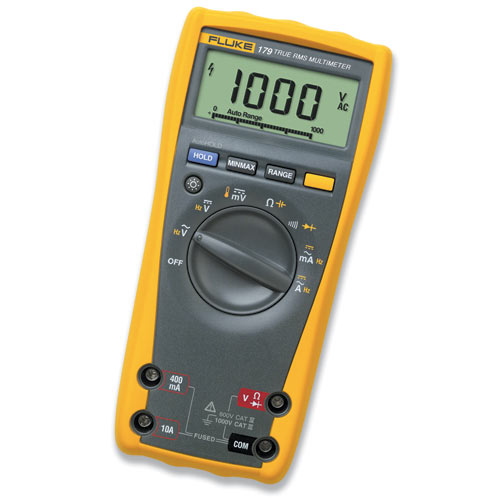
Most DMMs have the ability to measure temperature using optional temperature modules and probes. Some meters come with the temperature module already built in, such as the Fluke 179 and 16.
Continuity Test
Continuity is a quick go/no-go resistance test that distinguishes between an open and a closed circuit. The continuity test determines a good or blown fuse, open or shorted conductors, operation of switches, and circuit paths (by circuit or conductor tracing). A DMM with a continuity beeper allows you to complete many continuity tests easily and quickly without having to visually look at the meter each test. IMPORTANT: Keep in mind the level of resistance required to trigger the beeper varies from model to model of DMM.
Diode Test
A diode is like an electronic switch. It can be turned on if the voltage is over a certain level, generally about 0.3V for a silicon diode, and allows current to flow in one direction. If the DMM has a diode test, the readings across the diode should be 0.6V to 0.7V in one direction and indicate an open circuit in the other to indicate a good diode. If both readings are open circuit the diode is open, if both readings indicated continuity the diode is shorted.
Overload Protection
A circuit that protects the meter against excessive current at the input terminals can preserve your meter’s life and possible injury if excessive current is sent through. Some meters have overload protection that automatically returns to normal mode once the condition no longer exists. Others have protection that will not recover until the user replaces the fuse.
Auto/Manual Ranging
The ability to switch between measurement ranges automatically, usually in decade steps, or the need for the operator to do so manually. A range is a continuous band of signal values that can be measured or sourced, e.g. many meters have both a milliAmp range and an Amp range setting.
Backlight
This feature is a nice addition to a DMM that uses a backlit LCD to make it easy to read data in a dark electrical cupboard or low light environments.
Relative Time Stamp
This feature works in conjunction with the Min/Max record feature and allows you to time stamp certain maximum and minimum values to know exactly when the max and min values were encountered.
Multimeter Comparison Chart
|
DMM Safety Tips
• Use a meter that meets accepted safety standards.
• Use a meter with fused current inputs and be sure to check the fuses before making current measurements.
• Inspect test leads for physical damage before making a measurement.
• Use the meter to check continuity of the test leads.
• Only use test leads that have shrouded connectors and finger guards.
• Only use meters with recessed input jacks.
• Never touch the probes to a voltage source when a test lead is plugged into the 10A or 300 mA input jack.
• Select the proper function and range for your measurement.
• Be certain the meter is in good operating condition.
• Follow all equipment safety procedures.
• Always disconnect the “Hot” (Red) Test Lead first.
• Don’t work alone.
• Use a meter which has overload protection on the Ohms function.
• When measuring current without a current clamp, turn the power off before connecting into the circuit.
• Be aware of high current and high voltage situations and use the appropriate equipment such as high voltage probes and high current clamps.
• To avoid false readings, which could lead to possible electric shock or personal injury, replace the battery as soon as the battery indicator appears.
Info provide by Fluke Corporation
Go back to Tec Alert
Return to Top of Page
BUILD YOUR OWN TOOL KIT
Subscribe to our Tec-Alert Email Newsletter
Get tips & information for field service and MRO professionals.